Introduction
To create a physical data model that is flexible and extensible enough to allow applications to evolve without major changes, we must start by modeling the business. Specifically, modeling entities and their relationships, along with specialized attributes and associations such as inheritance. The artifact that captures reality in a very close way is the Domain Model. But unlike the definition available in Wikipedia, I’m focusing on the Rational Unified Process (aka RUP) that says:
“Incomplete business object model, focuses on explaining products, deliverables, or events that are important to the business domain. Such a model does not include the responsibilities people carry.”[1]
Still this definition is broad and leaves room for many interpretations. According to RUP, incomplete means that we are modeling business partially, without process models or business use cases. As a complement, we have the following definition from Martin Fowler:
“Visual representation of conceptual classes or objects from the real world in a domain of interest.”[2]
Wait, this definition is broad too. To be even more clear, we just represent business entities, their relationships and attributes. The definition of entity is also from RUP:
“In business modeling, business entities represent objects that business workers access, inspect, manipulate, produce, and so on.”[1]
It’s very important to know that we are modeling business, so it’s the current real world. But with those definitions we can model anything.
How to model a domain
The creation of a domain model is structured in the following steps[1]:
- List all candidate conceptual classes or entities
- Represent entities in a domain model
- Add associations between conceptual classes
- Add multiplicity
- Add attributes
I’m going to detail all steps. The modeling language will be Unified Modeling Language (aka UML) as it is closely related to RUP and have all semantinc elements to achieve the desired expressivity level. For the sake of completeness, the steps will include an example in a specific domain described as follows:
In a health sampling area, patients who must take exams are now received on a first-come, first-served basis or by scheduling. Each patient is called by a sample collector, who prepares all the necessary elements according to the patient’s clinical record and their need for tests. These elements are: supplies, tubes and necessary containers, according to the type of examination. For each tube or container used in a sample, the collector labels it to establish its origin and destination. Finally, the samples are delivered for dispatch to the corresponding laboratory, awaiting analysis and results.
1. List all candidate conceptual classes or entities
Here we can use the category list of conceptual classes[1] to identify them in the domain of interest. This list can be extended as needed.
| Category | Examples |
|---|---|
| Physical or tangible objects | Record, Airplane |
| Specifications, designs or descriptions | Specification of Product, Fly Description |
| Places | Store |
| Transactions | Sale, Payment, Reservation |
| Transaction details | Sale’s Detail |
| Roles | Cashier, Engineer |
| Containers | Store, Canister, Airplane |
| Things in a container | Passenger |
| External systems | Payment Authorization System |
| Abstractions | Anxiety |
| Organizations | Air Company |
| Facts | Sale, Payment, Meeting, Fly, Landing |
| Processes | Product’s Sale, Seat Reservation |
| Policies and rules | Cancellation Policy |
| Catalogs | Product’s Catalog |
| Financial, working, contract and legal records | Receipt, Account Book, Contract |
| Financial instruments and services | Credit Line, Stock |
| Handbooks, documents, books, reference articles | Repair Manual |
Additionally, we must apply the cartographer’s strategy[1]:
- Use existing names in the territory (domain)
- Exclude irrelevant features (entities, associations, attributes, etc)
- Do not add things that are not there (don’t invent things)
For instance, our domain model in a clinical context will have the following candidate conceptual classes:
| Category | Domain Entities |
|---|---|
| Physical or tangible objects | Syringe, Vacuum-Extraction Blood Tube, Urine Sample Container, Label, Vacuum-Extraction Blood Needle, Vacuum-Extraction Blood Tube Holder, Scalp Vein Set, Tourniquet, Kidney Dish, Sharp Container, Band-Aid, Cotton Ball, Procedure Gloves, Face Shield, Medical Mask, Goggles, Trash Can, Isopropyl Alcohol Bottle, Sterile Cotton Ball |
| Specifications, designs or descriptions | |
| Places | Blood Box, Urine Box, Waiting Room, Internal Laboratory, External Laboratory |
| Transactions | External Laboratory Services Purchase |
| Transaction details | Patient’s Basic Personal Information, Hospital Tributary Identification, Laboratory Exam’s Name |
| Roles | Patient, Sample Collector, Medic, Sample Collection Manager, Statistician |
| Containers | Vacuum-Extraction Blood Tube, Urine Sample Container, Sharp Container, Trash Can, Isopropyl Alcohol Bottle, Bag, Box |
| Things in a container | Blood Sample, Urine Sample, Syringe, Vacuum-Extraction Blood Tube, Urine Sample Container, Label, Vacuum-Extraction Blood Needle, Vacuum-Extraction Blood Tube Holder, Scalp Vein Set, Band-Aid, Cotton Ball, Procedure Gloves, Medical Mask, Isopropyl Alcohol, Sterile Cotton Ball |
| External systems | |
| Abstractions | Specialty |
| Organizations | Hospital, External Laboratory |
| Facts | Exams Order, Exams Order Entry, Exam Order Entry Status, Patients Schedule, Patients Schedule Entry, Patient Schedule Entry Status, External Laboratory Services Purchase Order, External Laboratory Services Purchase Order Entry, External Laboratory Services Purchase Order Entry Status |
| Processes | |
| Policies and rules | Clinical Supplies per Exam |
| Catalogs | |
| Financial, working, contract and legal records | Exams Order, Patients Schedule, External Laboratory Services Purchase Order, Exam Results, List of Daily Exams |
| Financial instruments and services | Stock for the following tangible objects: Syringe (100 units per box), Vacuum-Extraction Blood Tube (100 units per plumavit gravel), Urine Sample Container (100 units per bag), Vacuum-Extraction Blood Needle (50 units per box), Vacuum-Extraction Blood Tube Holder (20 units per box), Scalp Vein Set (50 units per box), Tourniquet (10 units per box), Band-Aid (100 units per box or bag), Cotton Ball (50 units per bag), Procedure Gloves (100 units per box), Medical Mask (50 units per box), Isopropyl Alcohol Bottle (50 units per box), Sterile Cotton Ball (50 units per bag).
Others: Critical Stock. |
| Handbooks, documents, books, reference articles |
2. Represent entities in a domain model
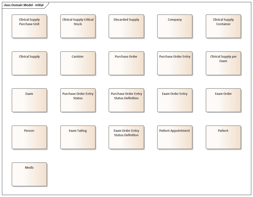
Now it’s time to diagram the identified entities in a domain model. This can be achieved by using UML class diagram in a simplified way: without data types, qualifiers and visibility indicators. The following rationale applies to representation:
- All the elements that control the stock are conceptualized as Clinical Supply (syringe, etc).
- The purchased units for each stock controlled element are conceptualized as Clinical Supply Purchase Unit (100 units per box, etc).
- The container in which comes the purchased units are conceptualized as Clinical Supply Container (bag, box, etc).
- Where clinical supplies are discarded is conceptualized as Canister.
- Hospital and External Laboratory are conceptualized as Company.
- Roles listed are conceptualized as Person (for personal data).
- All definitions for exams are conceptualized as Exam along with Clinical Supplies per Exam.
- For exams order’s record are conceptualized as Exams Order, Exams Order Entry and Exams Order Entry Status Definition.
- For patients schedule’s records are conceptualized as Patients Appointment.
- The external laboratory services purchase order is conceptualized as Purchase Order, Purchase Order Entry Status and Purchase Order Entry Status Definition.
Figure 1.1 shows the domain entities represented in a UML class diagram simplified:
Conclusions of part 1
By creating a domain model we achieve a deeper, better and shared understanding of the domain that is being represented. We can also communicate our ideas and thoughts about that domain thanks to the model.
The objective of this series of posts is to produce a final physical model in a target database. But there is still a long way to go. In the next part we will continue adding detail to the domain model in such a way to enrich it to refine the representation of the real world in context.
Your comments are important so we can share knowledge, ideas and thoughts about representation of entities in a domain model.
References
[1] Rational Software Corporation, Workflow Detail: Develop a Domain Model, 2001.
[2] Fowler M., Analysis Patterns: Reusable Object Models, 1996.

One thought on “Data modeling: from the concept to the physical model (part 1)”